
Week 4: Maya and 3d modeling
Artist research: Make Architect
MakeArchitect is an architecture firm with offices in London, Hong Kong, and Shanghai, the studio is renowned for its modern mindset rather than adhering to any specific style, it champions creativity.This also encourages the use of 3D models and 3D printers in its workflow, aiming to enhance the vividness and realism of project presentations. What sets them apart lies not only in their architectural projects but also in how they restructured their in-house model shop.
Under the leadership of Paul Miles (Model Shop Manager), Make moved away from an over-reliance on time-consuming, manual model-making techniques. Instead, they invested in a printer farm featuring 14 Ultimaker 3D printers running continuously
- Seymour Centre
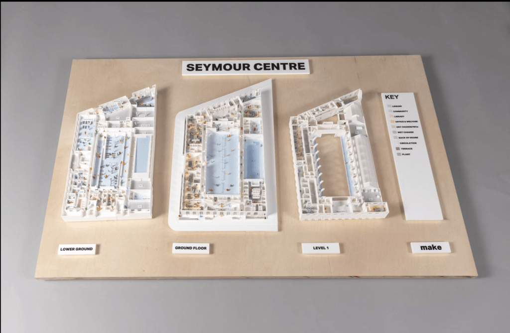
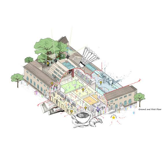
Instead of merely creating general massing models, they broke the structure down into sectional floor-plan components. They employs a white plastic material in general to eliminate visual distractions caused by color or texture. The focus is entirely on resolving the spatial layout, room proportions, and circulation patterns for various user groups such as swimmers, readers, and administrative staff. Here, 3D printing serves as a physical means of validating technical drawings that might otherwise seem abstract or dry.
I therefore recognize the effectiveness of 3D printed models. They are excellent for presentations and explaining functionality when intricate architectural details are not the primary focus, as they provide a clear overview of the project’s functional aspects. I find this presentation method more effective than using 2D drawings, as it allows clients to visualize the project much more clearly.
- Jersey South Hill
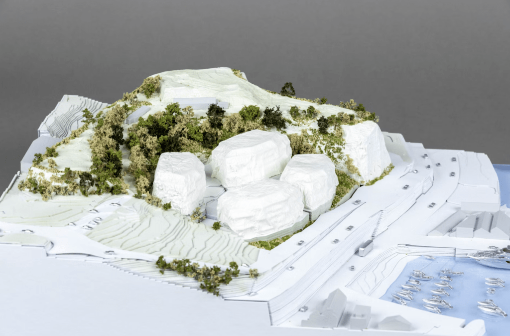
This project employed a variety of techniques and materials to create a vivid 3D model. Given the design’s strong connection to the surrounding landscape, incorporating the cliffs and harbor was crucial. Consequently, 3D scanning data was used to 3D-print the cliff forms; these served as masters for creating molds, into which plaster was cast to produce a seamless, smooth architectural volume that accurately replicated the terrain. The remainder of the base was constructed using layered cardboard to define the contours. Additionally, thin plaster sheets coated with acrylic were used to represent flooring and glazed levels, ensuring the design appeared natural and harmoniously integrated with the landscape.
I really appreciate this model due to the integration of various media in the modeling process. The final result is visually appealing and makes the design easier to visualize. 3D modeling is the optimal way to present a design, especially for architectural projects situated on rugged terrain, such as mountains or valleys.
Make Architects. “Paul Miles – Make Architects.” Make Architects, 5 Jan. 2024, https://www.makearchitects.com/maker/paul-miles/. Accessed 25 June 2026.
Artist research : LAVA
LAVA (Laboratory for Visionary Architecture) is renowned as a studio deeply rooted in the solarpunk ethos, integrating technology with architecture in its designs. They view architecture as a living entity that constantly develops and evolves alongside its surroundings. Their projects combine bold forms with cutting-edge technology to create spaces that are both functional and emotionally resonant. They used parametric modeling and many other 3D modeling in their projects.
LAVA (2016). Future By Design. [online] L-a-v-a.com. Available at: https://l-a-v-a.com/articles/future-by-design [Accessed 1 July 2026].
- KACST Innovation Tower (Saudi Arabia)
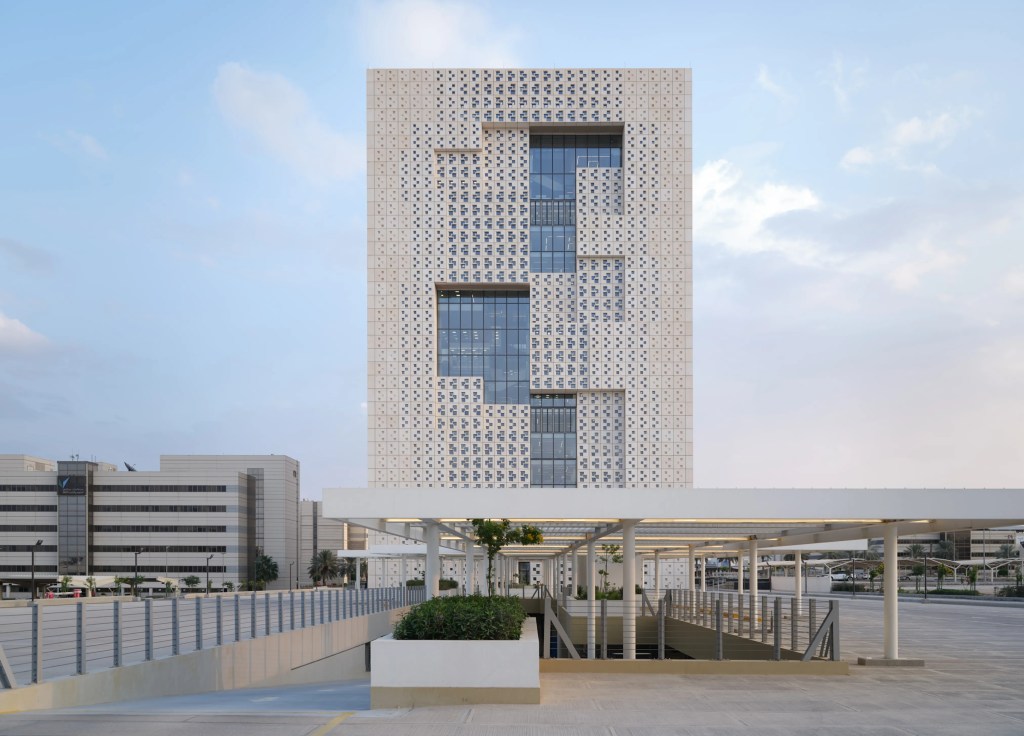
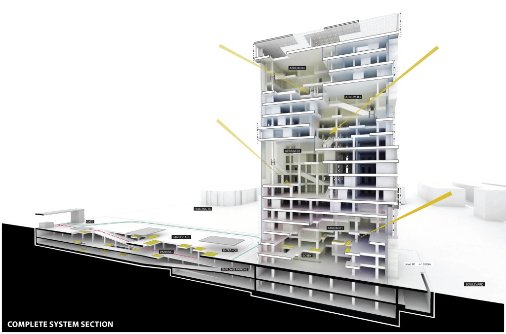
A precise solar-angle calculation model enables the building volumes to provide mutual shading, thereby drastically reducing the cooling load. Moving away from monotonous, monolithic office structures, the design establishes a multi-dimensional spatial hierarchy that fosters spontaneous interaction across different levels. Overall, the design features a distinctive massing with atrium cores that optimize natural light intake and heat dissipation, while also creating a strong connection to the surrounding topography. Rather than simply sitting as a box on the ground, the building extends into the subterranean levels to harness geothermal cooling, a strategy widely employed to address the Middle Eastern climate.
- The Snowflake Tower
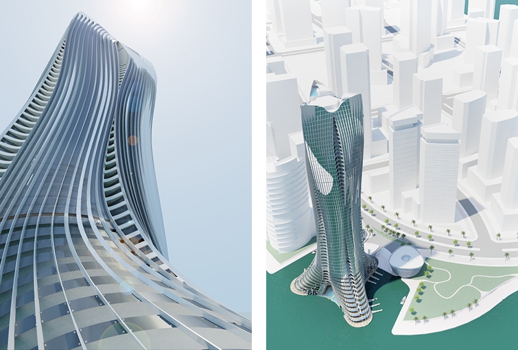
The architect applied the principle of minimal surfaces to optimize the ratio between façade area and floor area. Thanks to this spatial allocation algorithm, every apartment within the 59-story tower enjoys an unobstructed ocean view. The snowflake-like form was not manually drafted using conventional 2D tools; instead, it was generated using a polar coordinate system, where the boundary points of the floor plan are defined by angles and distances from the center. The complex conceptual mass was created using the Dynamo algorithmic software and then exported directly to the BIM platform, Revit. This integration allows the software to automatically segment the floor slabs at 5-meter vertical intervals while simultaneously generating a precise cladding system for the building’s exterior.
LAVA (2026). MSWCT Snowflake Tower » LAVA. [online] L-a-v-a.net. Available at: https://www.l-a-v-a.net/projects/mswct-snowflake-tower-2/ [Accessed 3 July 2026].
MAYA
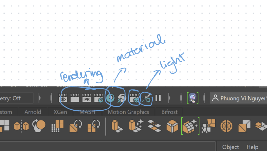
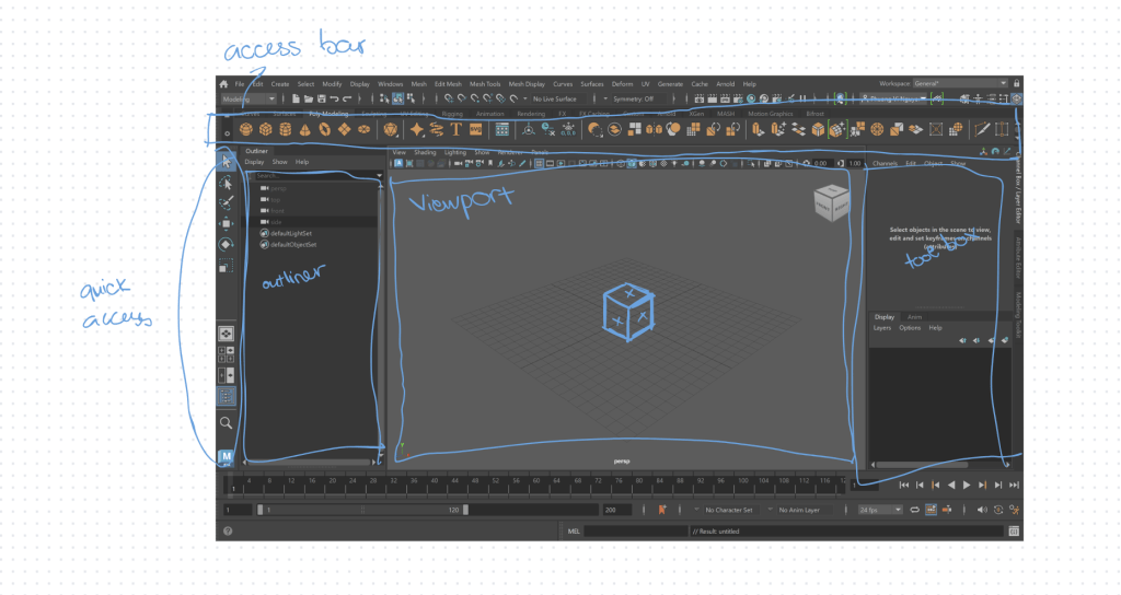
This is the layout of MAYA which have quick access, outliner, viewport, tool box (from left to right) and access bar on the top.
- some fuctions of maya
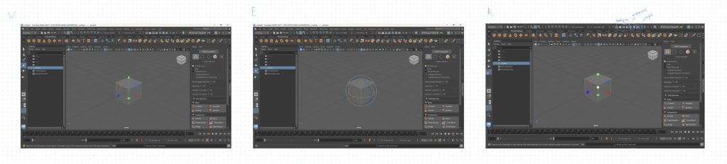
W / E / R : Move, Rotate, and Scale tools
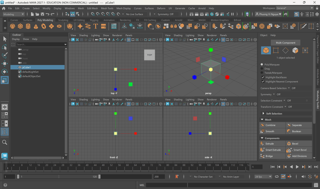
Space: See the four viewport layout
F: Focus on the object
Alt + right click: Zoom in/out
Alt + left click: rotate
Alt + shift + D: Delete history
Ctrl + E: Extrude -> creating depth, thickness, and complex geometry from flat surfaces.
Ctrl + B: Bevel -> creating rounded or chamfered edges to catch highlights and add realism.
Ctrl + D: Duplicate object
Ctrl + Z: Undo
Multi-Cut Tool: a manual tool used to add new edges to support the model’s structure. (Ctrl + click + shift: for even percentages)
Practice : MAYA
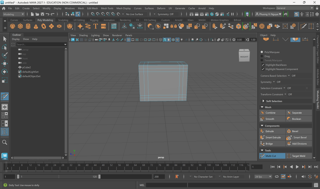
I created an object by using the square tool on the access bar then I setting the scale of the object by using R. After that I created new edges by using multi-cut tool (Ctrl + click + shift) in the even percentages.
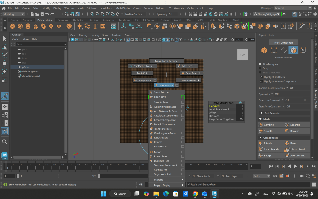
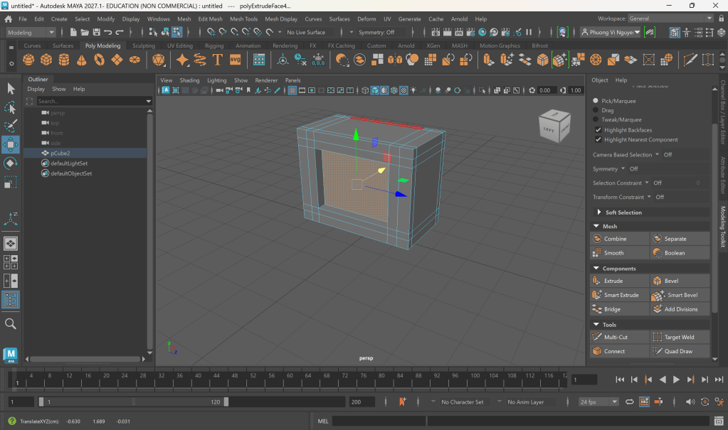
Then I switched to Face mode to select which face of object I wanted to choose.
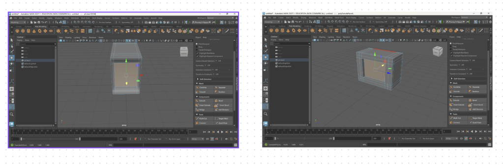
Then I used extrude tool to push the concave surface inward or outward.
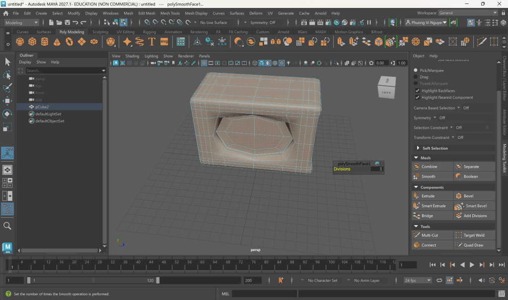
Here I used smooth tool
2. Fountain
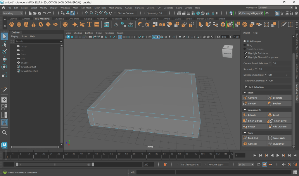
I created a big rectangle object and used multi-cut tool to create the foundation of a fountain.
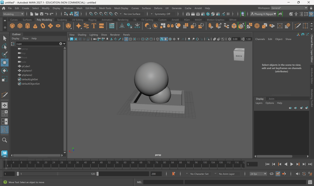
After using extrude tool to create a recessed foundation area, I create 2 sphere objects. I put the bigger sphere on the smaller sphere along a diagonal axis.
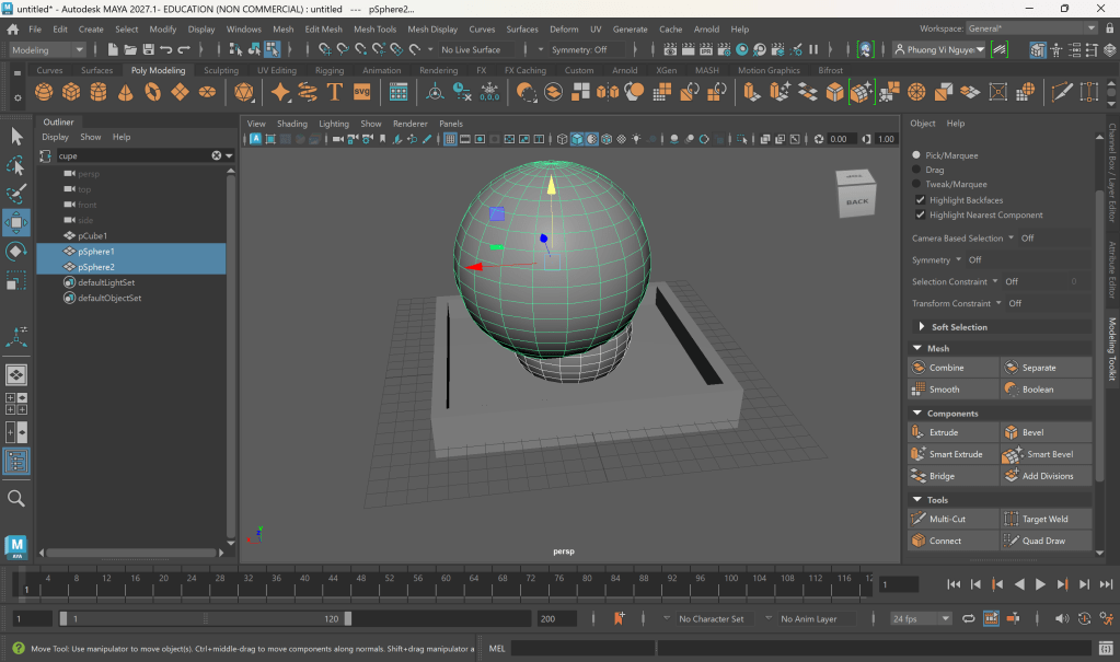
Then I selected both 2 objects and used boolean tools to make the bigger sphere cut a round cut onto the smaller sphere, I used this way because sphere has too many edge-cut to control or delete.
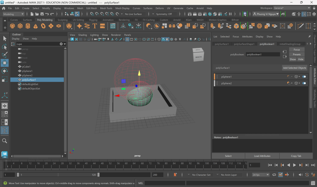
I can control the intersecting spheres using the bar on the right.
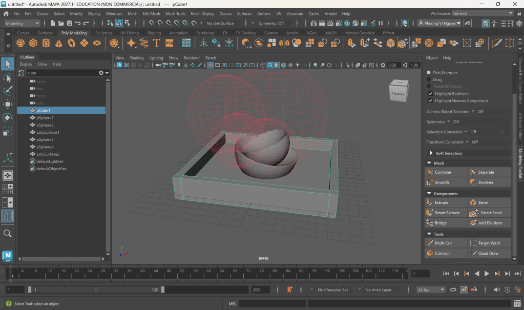
Then I did the samething with the second sphere. The hard thing here is controlling each layer. I’m having trouble accidentally moving unwanted objects.

